
Sign In
Welcome! Sign In to personalize your Cat.com experience
If you already have an existing account with another Cat App, you can use the same account to sign in here
Register Now
One Account. All of Cat.
Your Caterpillar account is the single account you use to log in to select services and applications we offer. Shop for parts and machines online, manage your fleet, go mobile, and more.
Account Information
Site Settings
Security
Designing Emergency and Standby Generator Systems
Consulting engineers who specify emergency and standby power equipment understand that installations for mission critical facilities, such as hospitals and data centers, are required to comply with NFPA 110: Standard for Emergency and Standby Power Systems, in conjunction with NFPA 70: National Electrical Code (NEC). System designers must interpret the requirements of NFPA 110, ensure their designs follow them, and educate their clients about how the standard affects their operations.
Richard Vedvik, KJWW Engineering & Daniel Winter, Faith Technologies
Learning Objectives
- Know the codes and standards that dictate the specification and design of emergency and standby generators.
- Consider various design, environmental, and commissioning aspects when designing generator systems.
- Understand the implications of specifying generators in mission critical facilities
Engineers of emergency power systems must be familiar with the latest requirements of NFPA 70-2017: National Electrical Code (NEC) and NFPA 110-2016: Standard For Emergency and Standby Power Systems. As these standards continue to evolve, as previous design approaches are evaluated over decades of service, and as retrofit projects encounter complications, the lessons learned by the industry must be taken into consideration to ensure modern emergency systems are safe and reliable. This article will focus on the applicable codes, environmental and operational design constraints, and considerations for health care and mission critical facilities while offering commissioning suggestions.
Applicable Codes and Standards
When applicable, engineers are required to consult code adoption of local municipalities, state authorities, and public health departments. This article will focus on professional design recommendations and the legal requirements associated with the latest available standards at the time of writing. Specifically, aspects of the 2017 version of the NEC and the 2016 version of NFPA 110 are referenced. Sections of the NEC that designers should reference include (but are not limited to):
- Article 110: Requirements for Electrical Installations
- Article 240: Overcurrent Protection
- Article 250: Grounding and Bonding
- Article 700: Emergency Systems
- Article 701: Legally Required Standby Systems
- Article 702: Optional Standby Systems
- Article 800: Communications Circuits.
Articles 700, 701, and 702 sometimes are confused. Looking at them in terms of increasing levels of importance, Article 702 is optional and usually used purely for backing up utility power, but not for life safety. Examples of optional standby systems include data centers or a commercial business resulting in discomfort, serious interruption of a process, or damage to a product. Article 701 covers issues associated with preventing hindrance of life-saving measures—for example, firefighting, ventilation, and smoke-removal systems. Article 700 covers issues associated with preventing loss of life. Examples are egress lighting, fire alarms, and fire pumps.


Environmental Design Considerations
Typically, emergency and standby generators are not deployed in ideal environments. Engineers must devise practical, actionable methods to deal with the environment in which generators are installed. The issues that must be dealt with include the general environment, ventilation, exhaust, fuel, acoustical, electrical clearances, locations, installation, and removal considerations.
Environment. When designing rooms that contain an emergency power supply (EPS) and EPSS, engineers should consider the possibility for natural or human-made disasters, including flooding by river, storm water, sewer, sprinkler system, flying debris, physical attack, and lightning as defined in NFPA 110, Chapter 7: Installation and Environmental Considerations. Mission critical equipment should never be relegated to areas that are prone to flooding, particularly below grade in basements. Although it may be a struggle to convince the design team and client that this equipment should be placed out of harm’s way, it will be worth it when storms hit and the critical equipment continues to operate. In addition to keeping equipment safe from flooding, fuel storage and filling locations also should be designed to allow for security and access during natural disasters.
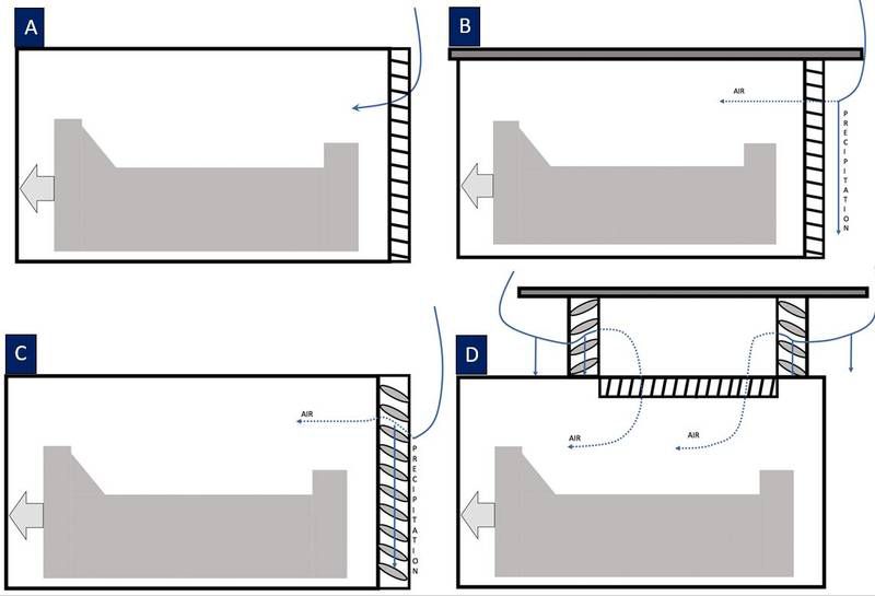
Ventilation. Generator sets require combustion and cooling air to enter the generator room or enclosure, and requirements are included in NFPA 110, Chapter 7.7.7. Most of the air is for cooling a unit-mounted radiator. Engineers must ensure the pressure drop of the entire system is within the manufacturer's recommendations, which will determine the size, configuration, and location of the air-intake pathways. When large or multiple generator sets are running, the amount of intake airflow can be significant. The layout of multiple generators should not result in uneven airflow distribution. In some instances, precipitation can be pulled into the controlled space. To prevent this, there are several design decisions that can help (see “Ventilation design considerations”).
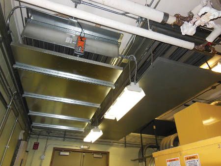
In designs where outside air is expected to bring in moisture and dirt, ceiling openings should include both drip pans and intake hoods and these openings should not be locatedabove EPS or EPSS equipment (see Figure 1). Engineers have the option of remote-mounted radiators, which greatly reduce airflow requirements for the room, but these systems will complicate the installation and may reduce engine cooling system reliability.
Exhaust. The exhaust system may require a Department of Natural Resources (DNR) study for the effects of exhaust dispersion using computational fluid dynamics, and engineers should be aware of where exhaust fumes may go (see Wisconsin DNR example). The proximity of the generator exhaust relative to the building air intakes for HVAC systems also requires careful study. Even when separated by several hundred feet, prevailing winds may bring the smell of generator exhaust into a building. When locating generators within a multistory building, the routing of exhaust piping will not only cause heat and noise concerns within the building, but also backpressure concerns for the generator set. U.S. Environmental Protection Agency Tier 4 compliance will require mitigation solutions such as urea injection or selective catalytic reduction, both of which reduce the amount of pollution.
Fuel. NFPA 110, Chapter 7.9: Fuel System covers requirements for fuel sources and references NFPA 30-2015: Flammable and Combustible Liquids Code and NFPA 54-2015: National Fuel Gas Code or NFPA 58-2017: Liquefied Petroleum Gas Code. Fuel sources located in the EPS room include local day fuel tanks or integral fuel tanks whose aggregate size is limited by the amount of fuel that can be stored in one room, defined as 660 gal by the International Fire Code-2015 Section 603 and reinforced by NFPA 110 Chapter 7.9. Requirements for main fuel storage is defined in NFPA 13-2011: Standard for the Installation of Sprinkler Systems and may be underground or aboveground fuel storage. The physical relationship of the fuel pipe routing to and from day tanks and larger storage tanks should be considered for optimum reliability, minimizing the need for solenoid valves on overflow and return lines.
While routed in the generator room, fuel lines should be protected but accessible. A common approach to this is in a grated trench that allows visual inspection, ease of maintenance, and provides some containment in case of a liquid fuel leak. Leak detection with monitoring by the building automation system is recommended in rooms without frequent observation. When routed outside and underground, the depth of frost in winter should be considered and fuel supply lines may require heat traces to prevent stagnant fuel from gelling.
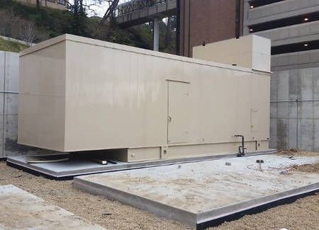
Acoustical. Noise from generator systems can disrupt building occupants or neighboring properties. Noise sources include generator exhaust, radiator cooling fans, electrical generator noise, and noise from the engine block. Vibration is a concern for locations within buildings. Common ways to reduce vibration within the structure include separate housekeeping pads and isolation springs with rubber mounting pads. Due to the high noise and vibration levels generated, it is not feasible to locate occupied spaces adjacent to generator rooms. Environmental noise is mostly from exhaust and the radiator fan. While there are many commercial options for exhaust mufflers, controlling radiator fan noise requires a custom approach. The engineer must understand the distances from air intake and discharge louvers to occupied spaces, such as offices, patient rooms, surgery departments, and residential neighborhoods. The primary pathway for generator surface noise and radiator fan noise is through intake and discharge air louvers. Achieving substantial noise reduction through these pathways requires sound attenuators or custom enclosures that are commonly oversized to minimize pressure drop, resulting in significantly larger space requirements (see Figure 2).
Electrical clearances. NEC Article 110 and NFPA 99-2015: Health Care Facilities Code identify clearances for EPS and EPSS equipment. Because required clearances vary based on the voltage present, engineers must know early in the design what voltages will be used. Medium-voltage generators may have wiring connection requirements that increase the size of associated cabinets.
EPSS locations. NFPA 110 allows the EPSS to be located within the EPS room. However, locating the EPSS in the generator room exposes it to moisture, dirt, and temperature extremes. Environmental discomfort for operational staff makes communication and operation of EPSS equipment difficult.
Installation and removal considerations. Because each unit requires installation through a large opening, it is common to rely on the cooling-air discharge or intake louvers as an installation path. Because future replacement is inevitable, the engineer also must ensure the generator can be removed without disruption to the entire system, i.e., removal of walls.
Operational Considerations
Engineers also must devise practical, actionable methods to deal with operational issues, such as loose materials, lighting, battery-charging systems, general inspections, and documentation. Engine-generators can often exceed hearing limits set by OSHA 1910.95: Occupational Noise Exposure. Therefore, earplugs and muffs are often required. Individual ear plugs can easily take flight while in the intake airstream. They should not land on hot areas of the engine or interfere with the radiator or radiator fan. Ear plugs and muffs should be placed outside of each entrance to the engine-generator space. This makes them convenient to don prior to exposure to harmful noise.
Objects that could take flight, such as manuals, paper, wood, and plastic, should be stored outside of the engine-generator intake-exhaust path—and preferably outside the entire room. Each type of material represents a risk to the generator radiator, exhaust fan blades, and fins, threatening the entire system.
Lights should never be chain-mounted. They should either be surface-mounted or suspended with solid hangers that prevent swaying and accidental damage. The types of light fixtures chosen should be capable of withstanding the environmental conditions of an EPS room. These fixtures should be capable of a wide operating temperature range as well as dust- and moisture-resistant. Lighting levels shall be suitable for detailed maintenance tasks. NFPA 110 requires battery-powered emergency lighting within the room.
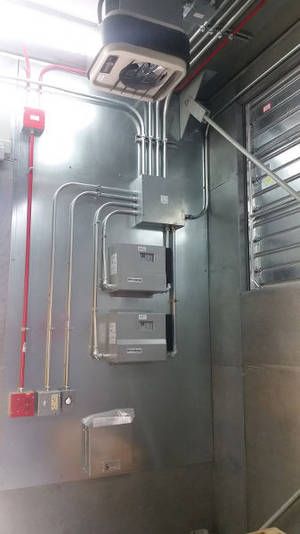
The battery-charging systems for engine-generators may be redundant, and the EPSS can choose which battery system to use for control power and automatic transfer switch (ATS) signaling. Redundant battery chargers also are referred to as “bestbattery systems” because they select the highest float-voltage battery to draw from (see Figure 3).
Prior to each planned use, engine-generators should be visually inspected, including fluid levels, battery voltages, fuel levels, and leak observations. Various problems can be easily detected prior to use. The prime movers typically are visually busy with connections, pipes, and curves, but they are usually symmetrical. With repeated practice, observing an errant or loose part becomes easier and worthy of a few moments.
Breaker numbering and labeling should be up-to-date so it is clear which circuit each overcurrent protective device (OCPD) is assigned. Typically, three- or four-digit numbers are far easier to recognize and process than a long strung-out breaker name. A current building or campus electrical diagram (one-line or riser format) should be wall-mounted at EPS and EPSS locations to provide operators with a quick reference. The one-line diagram should have breaker numbers next to each breaker. Breaker labels should include source, load, voltage, and normal position. The one-line diagram and breaker labels can be further clarified with colors for each system: red for emergency, black for utility, and various colors for downstream of each uninterruptible power supply (UPS) system or transfer switch.
Emergency systems for health care and mission critical clients are expected to have enhanced reliability. To meet the power and redundancy needs, paralleled emergency power systems are common. Paralleling systems increase complexity of design, commissioning, and operation.
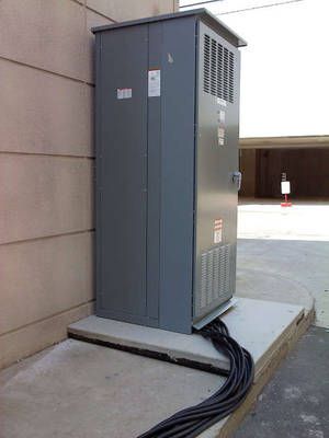
NEC added Article 700.3(f), which addresses emergency power outage mitigation for maintenance. Because the EPS is unable to provide backup power during periods of maintenance, the engineer must provide means for connecting a temporary EPS or provide a sufficient number of paralleled generators for an N+1 system. A common solution is an external generator connection cabinet on the building exterior (see Figure 4). This cabinet also can provide a convenient load bank connection to assist with generator testing if it is sized for the full load rating of the largest generator. External cabinets also allow connections to the system without requiring an electrical lockout of the EPS to prevent potential unexpected hot work if the engine-generators were called for during the maintenance activity. Because a trailer-mounted EPS requires block heaters and other electrical needs, a single-phase load center is typically included and the engineer must determine a power source for this panel. A temporary EPS must be monitored at attended locations, and should meet the same requirements as a permanent system.
NEC Article 517.31(C)(1) identifies the requirement for physical separation of overcurrent protection devices (OPCD) serving automatic transfer switches. This section requires life safety, critical, and equipment branch OPCDs to be in separate vertical enclosures, which increases the physical size requirement of the electrical distribution, meaning distribution that could fit in one switchboard section becomes three separate sections.
NEC expanded on Article 240.87 by clarifying how available arcing current may be taken into consideration when evaluating compliance for reduced clearing times. Generator manufacturers may be able to assist with compliance by monitoring for a fault condition and shutting down the alternator field current to reduce available arcing energy time. Selective coordination and arc flash considerations are beyond the scope of this article but are important topics of study, because misapplied designs can pose a threat to human life.
When designing switchgear or switchboards for paralleling or distribution, engineers must decide between two primary design choices: UL 1558 or UL 891. Within UL 1558, switchgear is the opportunity for arc-resistant construction and 30-cycle withstand ratings, both of which can improve selective coordination for clearing times below 0.1 seconds by allowing generator breakers to have instantaneous settings turned off. While improvements to selective coordination can be had with this approach, the need to provide arc energy reduction remains and available energy levels increase with delayed fault clearing times.
When engineers are sizing conductors, the use of 90°C ampacity tables may be desired. UL-listed breakers are limited to 75°C connections, which prohibit the use of 90°C termination ampacity values.
Medium-voltage generators are commonly 3-phase, 3-wire systems that require special consideration for bonding the neutral connection at the generator’s wye outputs. Bonding options include open, low-impedance, and high-impedance. A neutralto-ground resistor will require physical space and electrical clearances, which complicates the wiring configuration. An advantage to a 3-wire system is that it allows generators of different pitches to be paralleled. Because the pitch design has specific harmonics associated with it, paralleling different pitch 3-wire generators will introduce harmonics for both design topologies. While this approach is more common for 5-kV and 15-kV backup systems, it also can be applied for 600 V systems, specifically 480 V, 3-phase, 3-wire systems. This approach can offer the same generator manufacturer flexibility, but will commonly limit the building to 120 V lighting or separate 480 V to 480/277 V transformers for lighting panels. When discussing these options with the client, the engineer should consider the impact the additional complexity will have on long-term maintenance and operation.
Noise and vibration can be disruptive to patient sleeping areas and surgical departments where the tolerance for disruption is much lower than in other areas. EPS locations should be coordinated during programming and schematic design to minimize the cost associated with acoustical treatments and measures.
Regular generator testing can be disruptive to moneymaking activities, which commonly limits what times of the day or week staff can test the EPS and EPSS equipment.
When testing occurs at times of minimal activity, the actual building load is not known and reaching the required 30% loading may be difficult. The engineer should choose EPSS equipment that facilitates testing without disruption to the facility and allows staff to test with building load during peak activity times.
The 2015 version of NFPA 99 provides additional requirements for EPS and EPSS equipment and defines which level and class a facility will fall under, which is referenced in NFPA 110 for minimum run times. A Type 1 essential electrical system is classified as a Type 10, Class X, Level 1 generator set in NFPA 110 Chapter 4.
Critical Operations Considerations
Critical operations considerations include:
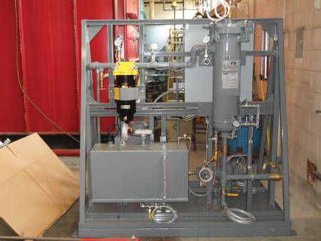
- Fuel. The large quantities of fuel maintained for hours of run time can go stagnant without proper chemical or polishing treatment (see Figure 5). Exterior storage should be heated or treated to avoid gelling in colder weather.
- Ride-through UPS systems.
- Physical security
- System redundancy.
System Commissioning
The following best practices should be considered when commissioning an engine-generator system:
- Factory testing may be attended by engineers and owners and is the first opportunity to see how the equipment will function. Attending the factory testing of paralleling gear is highly recommended, and the testing should include all possible configurations and possible outages so corrections can be made prior to shipping to the site. Factory witness testing also allows the owner to become familiar with equipment operation and ask questions directly to the manufacturer.
- Site-functionality testing is addressed in NFPA 110 Chapter 7.13. In addition to the requirements within Chapter 7, acceptance testing should include all scenarios possible, especially when multiple generators are in parallel. Minimal outage testing culminating in complete blackout testing is recommended to fully test programming and wiring. Testing through the transfer switch controls does not validate proper operation when utility power is lost. Of equal importance, the reaction to switching or momentary failure of power to mechanical systems must be verified to ensure controllers do not require a manual reset.
- During factory acceptance testing (FAT) and site acceptance testing (SAT), the engineer should be developing and honing methods of procedure (MOP) that create a clear step-by-step checklist for performing commonly repeated tasks or switching operations. The MOP should be developed to match or improve the end user’s documentation. The purpose is to clearly document steps, so that during times of stress or when training new operators, the steps are clear, repeatable, and proven. It is common to include screenshots of digital control panels showing before and after one-lines and breaker positions. These directions also should include steps to enforce the client’s lockout/tagout (LOTO) procedures. It is often helpful to total the number of locks required for an MOP at the beginning so they may be acquired prior to being needed. Also, the MOP could highlight when an action represents an arc flash hazard. This can provide a necessary reminder for those who need personal protective equipment to don it, and those not protected to vacate the arc flash boundary.
- Documentation including shop drawings, descriptive, concise, clear MOPs, and labeling should be in readily accessible locations.
- For continued safe operation, it is vital that the owner’s facility staff understands how the system works and how to manually connect generators to the EPSS. Engineer and owner participation during training should encompass factory acceptance through commissioning to ensure confident operation.
- Manual and automatic syncing should be reviewed until it is familiar by staff. The emphasis on manual mode cannot be understated. Operators should be aware of and familiar with what an automatic system is doing.
- During SAT, the operators should be strongly encouraged to participate in the physical actions. The sensory lessons learned during these actions will help detect mechanical wear or incorrect operation in the future.
To prevent precipitation, which can be pulled into controlled spaces when multiple generators are bringing in significant airflow, consider these four design configurations.
Design A represents a minimalistic exterior enclosure with typical air-intake dampers that allow the most moisture ingress.
Design B represents a building with a soffit or overhang above the air-intake damper. The air-intake penthouse and airfoil louvers minimize moisture ingress.
Design C represents an exterior enclosure with airfoil louvers sized for a sufficient louver-free area to minimize air velocity, which minimizes or prevents falling precipitation from being pulled into the space.
In climates where snow is a concern, Design D illustrates an air-intake penthouse that can be constructed with louvers that provide adequate distance between the louver and the generator, which allows precipitation to fall out of the airflow path. This interstitial space should include adequate heat to melt snow and ice and heat-traced drains to remove the resulting runoff. Louvers designed to withstand serious weather events, such as hurricanes, can also be used to protect the space from flying debris while providing water-shedding capabilities with specially designed flow paths that collect the water and channel it out of the airstream.

